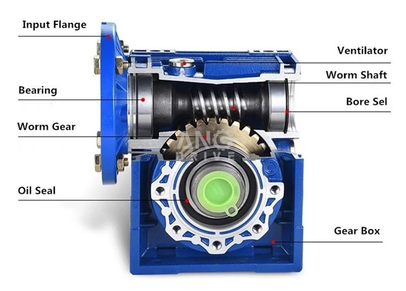
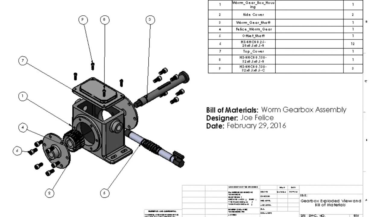
The exploded diagram of the worm gear box assembly. The parts are as
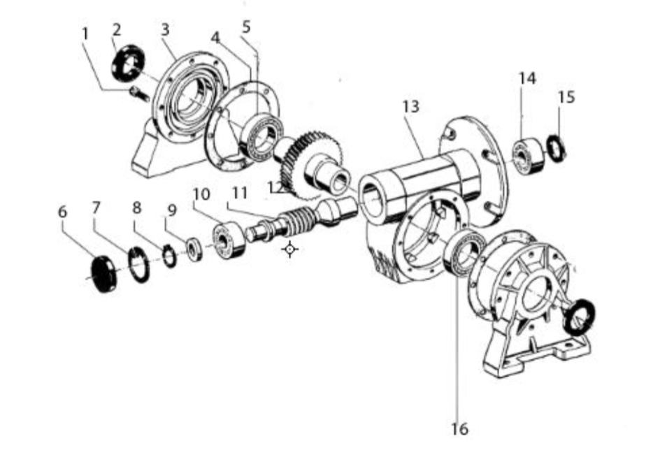
Download scientific diagram | The exploded diagram of the worm gear box assembly. The parts are as follows: 1-cover; 2-bearing; 3-worm shaft; 4-cover; 5-bearing; 6-gear box body; 7-bearing; 8-oil seal; 9-cover; 10-plug; 11-worm gear rim; 12-worm gear hub; 13-output shaft; 14-bearing; 15-oil seal; 16-cover from publication: Image-assisted collision detection for calculation of an assembly interference matrix | The assembly interference matrix is a foundational information model for assembly process planning such as assembly sequence and assembly path planning, and supports digital assembly simulation, intelligent assembly, digital twin-based assembly, and so on. The assembly | Collision Detection, Assembly and Matrix | ResearchGate, the professional network for scientists.

The exploded diagram of the worm gear box assembly. The parts are as
gearboxes
Solved An exploded view of the VF30 Gearbox is shown below

DC GEAR MOTOR/DC MOTOR Doncen Motor

Worm Gear, Gearbox, Worm Reducer Manufacturer & Supplier India Elecon
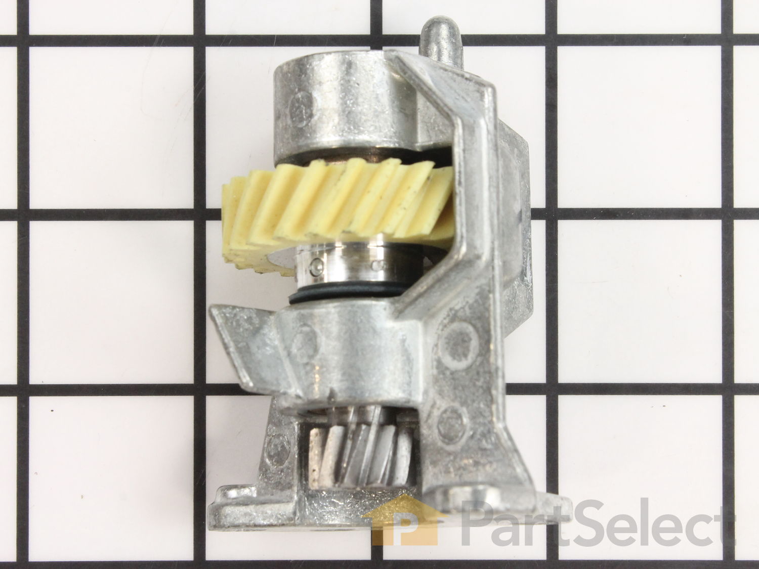
Worm Gear and Bracket WP240309-2, Official Whirlpool Part, Fast Shipping
MTD 31AH5DV8897 CA328 (2018) Parts Diagram for Auger Gearbox Assembly

GN 3975 Worm Gear Reducers, Aluminum
The exploded diagram of the worm gear box assembly. The parts are as
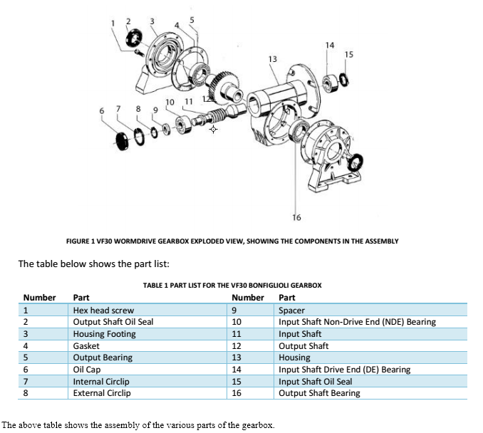
Solved 15 13 10 11 6 7 8 9 FIGURE 1 VF30 WORMDRIVE GEARBOX
Gearbox Motion Study and Drawings
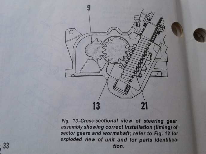
Sector timing - reassembly of steering box
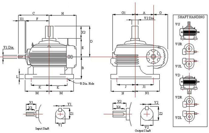
Vertical worm gear box dimension, Agnee worm gearbox